Thu, 19 Dec 2013
Arduino SCX Digital to USB interface
I have a SCX Digital slot cars set, and some years ago I bought an interface box for connecting it to the PC using a RS-232 serial port. PC then can be used as a timer, lap counter, and race management. Now I wanted to make some modifications to the firmware (it uses AVR Tiny 2313 chip). I have discovered that the author does not sell this version anymore, it has been replaced by a newer version with USB. So I kindly asked the author whether he can provide me the source code for the firmware for the old version. I have got the following reply:
Hi Jan
Sorry, I do not share any of my software.
Well, whatever. It is of course his choice to keep the firmware of the abandoned version for himself. But in the meantime, I've got some experience with electronics and microcontrollers (see my other projects).
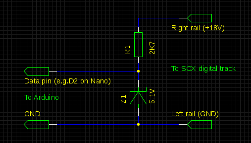
Introducing SCXreader, my own SCX-to-PC/USB interface, built with Arduino Nano. It is fully open, including the source code of the firmware. It costs about US$ 6.50, way less than the current SCX-to-USB SEB interface.
8 replies for this story:
Tomáš Pecina wrote: What about the clamping diode?
Myself, I wouldn't go for this. There is a clamping diode between the data pin and VCC, and I don't think it is a good idea to expose it to currents of more than 5mA when VCC is grounded. A lot of heat to dissipate for a tiny little diode...
Yenya wrote: Re: Tomáš Pecina
I do not understand. The data pin is configured as an INPUT pin, so there is no way it can source any significant current when Vcc is grounded (I suppose that by Vcc you mean the Right rail pin). And also note that the diode is not between Vcc and the data pin. Anyway, this configuration is tested, and I have verified there is no significant heat generated.
Tomáš Pecina wrote:
No, there is a protection diode between any pin and VCC of the embedded processor (I don't know which Arduino model you use so I cannot look up the catalog data). If Arduino is powered down, the Zener diode will stay closed and all the current (of some 6 miliamps) will go right through the on-chip diode in Arduino. Take a meter and measure the voltages on R1 and Z1 when VCC=VSS and you'll get a picture.
Yenya wrote: Re: Tomáš Pecina
Ah, I understand now. Two objections: 1) why would I clamp Vcc to GND? At the worst case, Vcc will be left floating, not clamped anywere. And 2) even if I will connect Vcc to GND, the current is limited by R1 resistor, so it would be at most 6.66 mA. Given that ATmega328 pins can source and sink up to 40 mA for each pin, I would guess that even the current between the data pin and Vcc pin of ATmega going through the protection diode should withstand similar currents. 6mA is not so much in terms of ATmega GPIO pins.
Yenya wrote: Re: Tomáš Pecina
One more thing: the protection diode is - well - a diode. Provided that it directly connects the pin and Vcc, clamping Vcc to ground and having the pin connected to +18V via 2K7 resistor would mean that the total power dissipation on ATmega would be proportional to the forward voltage drop on the protection diode. Which is - i guess - somewhere between 0.25 and 0.5 V. For 6.6 mA current, the power burned inside the MCU would be somewhere around 3 mW, which is way less than the MCU normally handle. The rest would be burned at the resistor outside the MCU. So I think even connecting Vcc and GND on the MCU side would not bring any significant problems.
Tomáš Pecina wrote:
1. Wrong. VCC won't be left floating, if the power supply is disconnected, it will power the whole Arduino plus any peripherals you may have left hooked up. Some designs are based on this setup (see, eg, http://hackaday.com/2009/06/27/avr-rfid-tag/). 2. The AVR can sink up to some 50 milliamps, right, but the path is through an open CMOS transistor with negligible voltage, not through a junction, which has some .65 volts of residual voltage on it. I'm not saying your circuit is going to destroy the AVR, only that it is a flawed design and definitely not in compliance with the catalog values under which the chip may be safely operated, ie, something I would never do to any of my three beloved Arduinos :-)
Yenya wrote:
I got a multimeter, unplugged Nano from the USB port (leaving it plugged to the above mentioned circuit. The voltage between the data pin and GND is not very stable, but it oscilates between 0.3 and 0.4 V. Which is well inside the specs: the datasheed says that the maximum voltage on the data pin should be Vcc + 0.5 V.
Tomáš Pecina wrote:
Great! So Z1 is closed and the +18V is sourced, via R1, right into the protective diode, the current trough it being approx. 7mA. My recommendation is to insert a 27K resistor between D2 and the cathode of the Zener, which will make your design safe and robust, with negligible impact on its function.