Connect your SCX Digital slot cars track to the PC over USB, and use the PC as a timer, lap counter, race management, etc. Fully open design, costs only 5 €, or US$ 6.50 to build!
Bill of Materials
- Arduino Nano (I bought one for US$ 6.16 here on eBay, shipping to the Czech Republic included). Any other Arduino or ATmega88/168/328-based board can be used as well, probably with minor tweaks to the firmware. In fact, many other Atmel AVR chips should work too: the firmware requires only the hardware UART/USART, one pin for data, precision clock using crystal, and a 16-bit Timer/Counter. Arduino Nano is just the cheapest option with USB-to-serial interface and crystal included.
- Zener diode (rated 5 V or 5.1 V, as small as possible; I used 5.1 V, 0.5 W bought at GES Electronics for 1 CZK, or about US$ 0.05)
- 2K7 resistor (0.125 W rated should be sufficient)
- Miscellaneous (two-line copper cable, solder, etc.)
Schematics
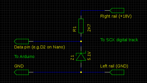
Since SCX Digital works with a much higher voltage than Arduino can handle, we need to clamp the voltage to about 5 V using a resistor and a Zener diode. So we need a 5 V-rated Zener diode. The resistor value should be small enough to keep the Zener diode in the breakdown state. These small diodes need about 5 mA to remain in the breakdown state. The SCX track runs at 18 V, so we need to have 18-5=13 Volts on the resistor, which with 5 mA current gives 13/0.005 = 2600 Ohms. So a 2K7 resistor should be OK.
That's it, everything else can be done in software!
Wiring
The interface can be connected anywhere on the track. The left rail (in the direction of the cars) is ground, the right one is +18V/signal. In order to avoid the signal noise, I recommend to connect it as close to the controller unit as possible. In fact, I have connected mine directly to the Start/Finish track:
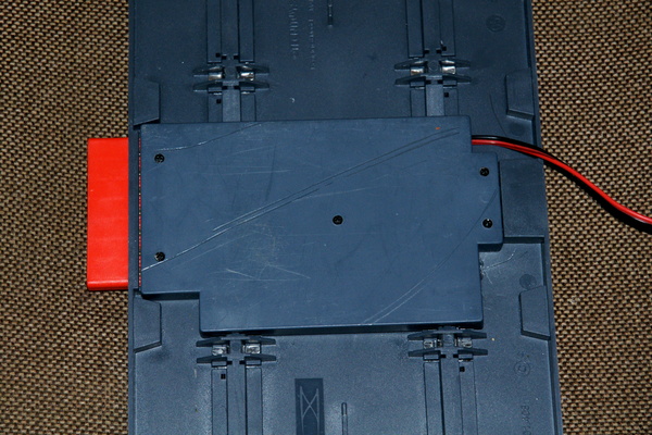
Unscrew the cover in the middle of the S/F track (5 screws). It is possible to connect the interface to the track, or to the solder pads of the orange connector (which is much easier to solder):
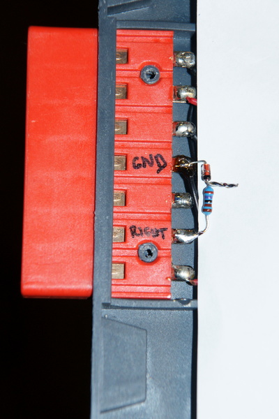
Twist the cathode wire of the Zener diode together with the resistor wire and solder them to each other. Solder the anode of the Zener diode to the middle pin of the orange connector, and the remaining wire of the resistor to the second pin from the bottom. For clarity, I have put a sheet of paper under the soldered parts in the above picture.
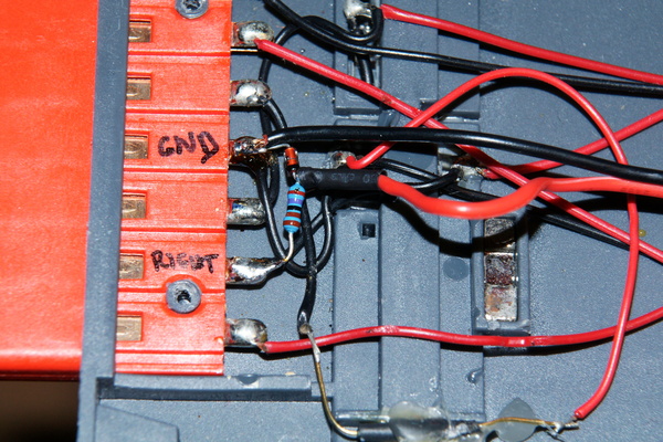
Now get the two-wire cable, and connect one wire to the middle pin of the orange connector (GND), and the other one to the twisted and joined wire connecting the resistor and the Zener diode cathode. I used black wire as GND and red one as signal.
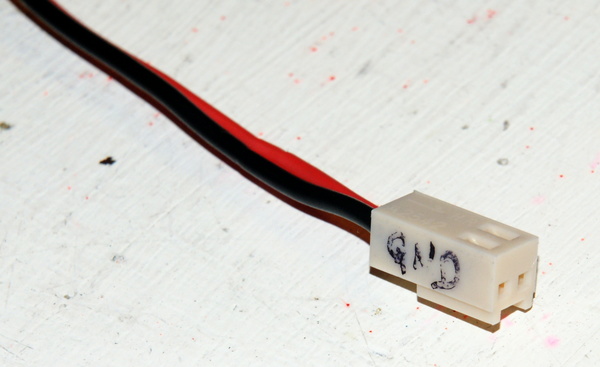
The opposite end of the cable can be soldered directly to the Arduino. I want to use my Arduino for other purposes as well, so I went for a connector. Mind the polarity, of course.
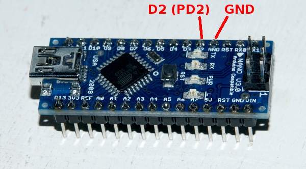
For the signal pin, any Arduino/ATmega digital pin can be used. Since I used the connector, I went for a pin next to the GND pin, which is D2 (PD2 on ATmega).
Firmware
The firmware is distributed including the source code under the terms of the GNU General Public License, version 2 (only). There are several ways of getting the firmware:
- Get the precompiled version set up for
the PD2 pin. Upload it to Arduino using the following command (some
options can be different on different host operating systems, of course):
avrdude -patmega328p -c arduino -P /dev/ttyUSB0 -b 57600 -U flash:w:scxreader.hex:i - Get the source code from the
Git repository:
git clone https://www.fi.muni.cz/~kas/git/scxreader.git
compile it, and upload it to Arduino:
cd scxreader

make

make program_flash
Use It!
The interface is compatible with Ole Seeberg's (SEB) interface, so it can be used with any race management software, which is compatible with the SEB interface. I have my own race management software for Linux called Slotcarman, which I intend to publish soon (send me an e-mail if you want to be an early tester). Then there is PC Lap Counter and others.
Motivation :-)
... or Why Did I Create This:
I have an old SEB serial interface (which uses ATtiny2313 without a crystal and MAX232 level-shifting chip). I wanted to do some modifications to the firmware. Because Ole Seeberg does not sell this version anymore, I thought he could provide me the firmware source code. So I have asked him by e-mail. His reply was this:
Hi Jan
Sorry, I do not share any of my software.
Sincerelly
Ole Seeberg
So I went and build my own interface with my own firmware, and I am publishing it for others to use and modify. Mine is fully open source, and costs about US$ 6.50 to build, Ole Seeberg's one is proprietary, and costs about US$ 98, or 73 €. Choose whichever you want :-)
Links, resources
- Arduino Nano
- ATmega 88/168/328 datasheet
- SEB interface
- Slotcarman race management software
- PC Lap Counter
- SCX Digital protocol description (in German; here is the Google translation)